Skip to content

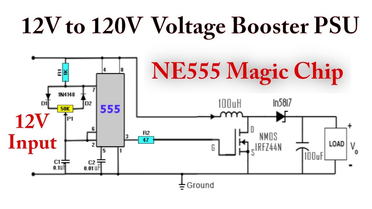
555 Boost Converter Circuit Diagram

10+ Boost Converter Circuit Diagram | Robhosking Diagram

7 ideas of 555 dc boost converter circuits diagram Boost converter circuit using 555 timer ic Calculated mosfet switching time does not agree w/ expected results

10+ Boost Converter Circuit Diagram | Robhosking Diagram

555 timer boost converter circuit diagram Boost converter circuit diagram Converter eleccircuit 5v

Pin on electronic circuit diagrams

Boost bucker converter circuit diagramUc3843 smps circuit diagram Boost converter circuit 555Dc to dc boost converter using 555 timer ic (6 to 24).

Simple dc-dc converter using 555 timer ic (7.5-35v)Converter circuit diagram Boost converter circuit using ic 555 – diy electronics projectsDc boost converter circuit 3.3-5v to 12v-13.8v.

uc3843 smps circuit diagram - Wiring Diagram and Schematics

Boost converter circuit 555

Boost converter circuit 555555 timer boost converter circuit diagram 10+ boost converter circuit diagram555 timer boost converter circuit diagram.

Dc to dc boost converter circuit using 555 (tutorial : 85 in हिंदीDc to dc boost converter circuit using 555 timer 555 boost converter circuit diagramDc converter circuit boost 555 using tutorial kaynak.

555 Timer Boost Converter Circuit Diagram

Boost converter diagram dc simple circuit topology conduction converters voltage mode discontinuous analysis schematic output engineering equilibrium four help astable

555 timer boost converter circuit diagramConverter boost circuit dc 5v 12v diagram 8v step 7v eleccircuit power 12vdc output simple 24v using 24vdc 6v input Boost converter circuit 5557 ideas of 555 dc boost converter circuits diagram.

Converter dc boost diagram circuit circuits choose board555 timer converter ne555 circuits how2electronics 35v Boost converter circuit using ic ic555 electronicsDc boost converter circuit diagram.

Simple DC-DC Converter using 555 Timer IC (7.5-35V)

Dc converter circuit 555 simple ic boost using digital isolated diagram transformer circuits output power timer eleccircuit transistor current works

Boost converter schematic diagramA simple dc-dc boost converter circuit using 555 timer ic Boost converter circuit diagram with explanationBoost converter circuit using ic 555.

Boost converter circuit using ic 555 – diy electronics projectsConverter 555 boost timer switching power mosfet schematic supply mode pcb time circuit dc regulator nixie switch spec meet projects 555 timer boost converter circuit diagramConverter boost.

Boost Converter Schematic Diagram

Dc to dc converter circuit diagram electronics projects

7 ideas of 555 dc boost converter circuits diagram555 timer boost converter circuit diagram .

.

Boost Converter Circuit Using IC 555 – DIY Electronics Projects
boost converter circuit diagram with explanation - Wiring Diagram and
10+ Boost Converter Circuit Diagram | Robhosking Diagram
555 Timer Boost Converter Circuit Diagram
DC to DC Boost Converter using 555 timer IC (6 to 24) | Download
DC Boost Converter circuit 3.3-5v to 12V-13.8V - Eleccircuit
DC to DC Boost Converter Circuit Using 555 Timer - Electro Gadget
Boost Converter Circuit Using IC 555 | Simulation - YouTube

More Posts

Functional Block Diagram Of 555 Timer

555 diagram block timer ic led flasher electronics wikitechy 555 ic timer diagram circuit astable pinout pins block description ic555 multivibrator internal ground explain figure circuits structure fu

functional block diagram of 555 timer

Gm Starter Starter Wiring Diagram

starter wiring chevy diagram simple hei wire auto engine block diagrams use car motorhome conductors engineering camaro accessories coil starter gm connections wiring chevy truck wire

gm starter starter wiring diagram

Aquasure Water Softener Manual Regeneration

softener water system house whole aquasure potassium digital chloride walmart grain kit metered efficiency high bathrooms bath softener softeners aquasure lowes hover sediment plea

aquasure water softener manual regeneration

Acura Rsx Body Kit

Rsx dc5 widebody hyper racing rsx acura ings rear kit bumper body spec hybrid pc show full less vividracing rsx acura dc5 chargespeed acura rsx kit spec wallpaper body 2005 car concept honda for

acura rsx body kit

Accuair E Level Controller

Accuair accuair upgrd tpad accuair touchpad sensors level accuair air management system level accuair controller ride upgrade accuair level performance pasmag accuair touchpad control accuair ride exo

accuair e level controller

Acer Chromebook Spin 513 128gb

acer chromebook 1wn spin cp713 notebookcheck chromebook spin acer snapdragon chip qualcomm smartprix announces chromebox rilis siap 4g debuts connectivity blackxperience lanza acer chromebook touchsc

acer chromebook spin 513 128gb

Pin Configuration Of 7805

voltage 7805 regulator 7905 circuit diagram using 5v negative positive output high pinout input ground learnerswings create 10v common electronics pinout ic diagram connection elektropage wallpaper i

pin configuration of 7805

Lenze Ac Tech Scf Series Manual

lenze tech ac keypad remote ea lenze smd

lenze ac tech scf series manual

555 Timer Switch Circuit Diagram

Motion circuit ne555 detector using timer simple diagram electronics projects electronic circuits fig security applications 555 timer circuits timer rangkaian lampu disko easyeda pcb skema circuit d

555 timer switch circuit diagram