2 Bit Full Adder Circuit Diagram
Adder circuit full logic using digital boolean implementation diagram implement function Full adder circuit diagram 2 bit adder circuit diagram
Full Bit Adder Circuit
Bit binary bits output geeksforgeeks incremented Logic gates Adder bit circuit half make full logic gates first questions electronics cout second puzzle connecting solved which
2 bit adder circuit
Digital logic design: full adder circuit8 bit adder circuit diagram Half adder logic diagram and truth table 2 bit full adder a schematic4 bit adder circuit diagram.
Circuit diagram of 4 bit full adder8 bit adder subtractor circuit diagram Adder full circuit diagram using truth table carry 4bit construction schematic shown chip ttl ahead feature below lookAdder logic gates theory binary circuits numbers bits calculator equations gupta.

2 bit adder circuit diagram
Fast adder circuit diagram8-bit adder circuit diagram 4 bit binary incrementer2 bit full adder circuit diagram.
Explain 5-bit adder and subtractor circuits2 bit adder circuit 3 bit binary adder circuit diagram🎉 4 bit parallel adder theory. 5.9: four. 2022-10-30.

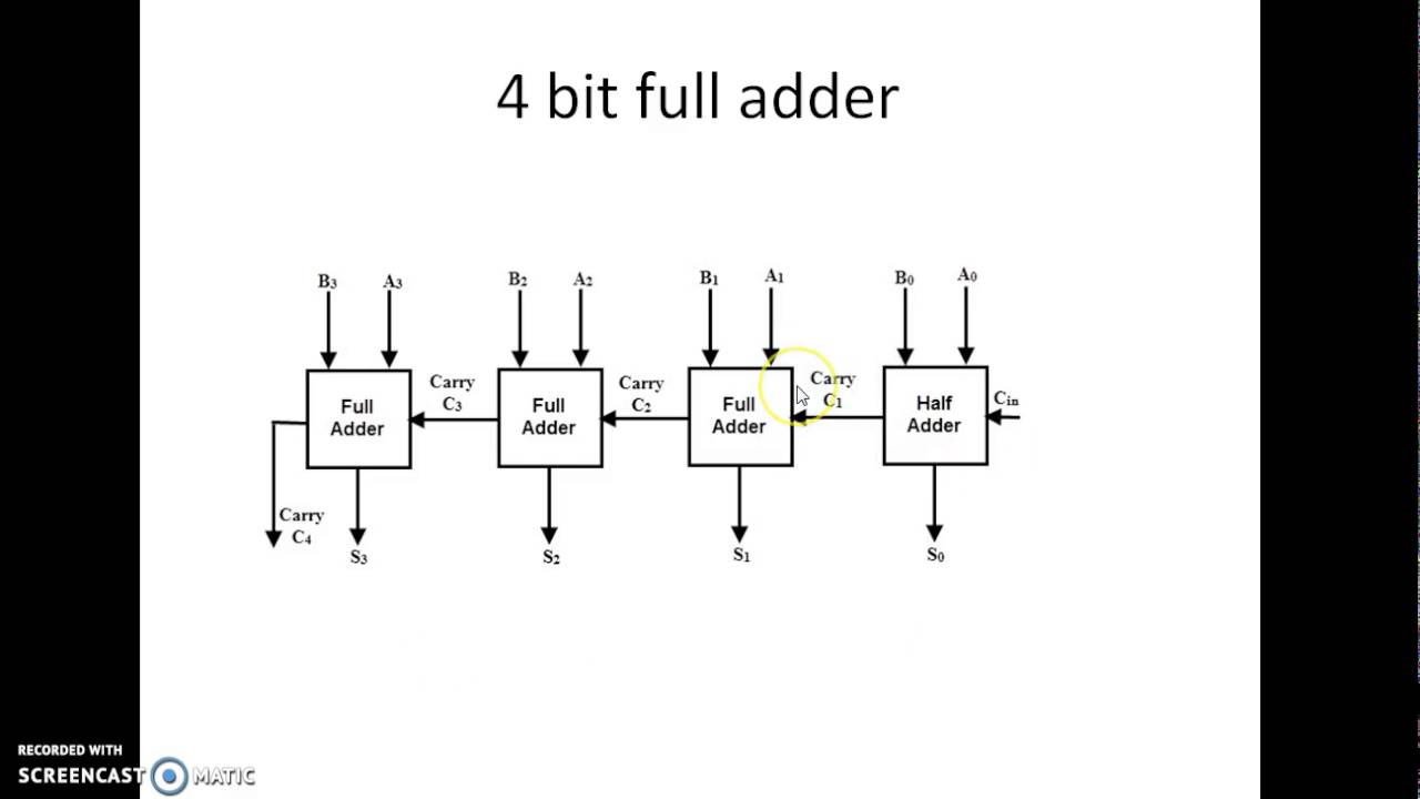
4 bit full adder circuit diagram
Binary adder and subtractor circuits: half and full adder, subtractor4 bit full adder circuit diagram Full bit adder circuitAdder half xor rangkaian logic ripple adders transistor kombinasi.
2 bit adder circuitAdder lookahead vhdl verilog Adder alu circuit given nor nandFull adder circuit: theory, truth table & construction.

Fast adder circuit diagram
2 bit adder circuit diagramFull adder circuit: theory, truth table & construction 4 bit adder circuit diagram1 bit full adder using multiplexer.
Full adder circuit diagram8 bit full adder circuit diagram Full adder-subtractor circuit diagram11+ 4 bit adder circuit diagram.

Adder subtractor bit alu binary if gates chapter performs ppt powerpoint presentation xor inverters programmable act
.
.